English
 Espaol
 Franais
 阿拉伯
阿拉伯 中文(簡)
中文(簡) Deutsch
 Italiano
 Português
 日本
日本 韓國
韓國 български
 hrvatski
 esky
esky Dansk
Dansk Nederlands
 suomi
suomi Ελληνικ
 印度
印度 norsk
norsk Polski
 Roman
Roman русский
 Svenska
卡特彼勒3512發(fā)動機調(diào)整
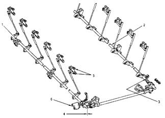
卡特彼勒3512發(fā)動機調(diào)整程序 1.單體泵齒條同步行程調(diào)整程序 2.尋找活塞在第1缸上止點 3.氣門過橋調(diào)整程序 4.氣門間隙調(diào)整程序 5.氣門和氣門橋調(diào)整工具 6.單體泵正時調(diào)整程序 卡特彼勒3512發(fā)動機設計 卡特彼勒3512E發(fā)動機技術規(guī)范 卡特彼勒3512 Crankshaft Position for Fuel Injector Adjustment and Valve Lash Setting卡特彼勒3512單體泵和氣門閥調(diào)整順序 Counterclockwise rotation –CCW. (Standard) from the flywheel end of the engine面向飛輪曲軸轉(zhuǎn)動方向逆時針方向運轉(zhuǎn)(標準運轉(zhuǎn)) Inlet Valves 空氣進氣閥 Exhaust Valves 排氣閥 Injectors 單體泵 No. 1 Piston At Top Center Position 活塞在第1缸上止點 1-3-6-7-10-12 1-4-5-6-9-12 2-4-5-8-9-11 No. 11 Piston At Top Center Position 活塞在第11缸上止點 2-4-5-8-9-11 2-3-7-8-10-11 1-3-6-7-10-12 Standard rotation CCW 標準逆時針方向運轉(zhuǎn)點火順序 1, 12, 9, 4, 5, 8, 11, 2, 3, 10, 7, 6 Inlet 進氣閥調(diào)整 0.50 mm (0.020 inch) Exhaust 排氣閥調(diào)整 1.00 mm (0.040 inch) 卡特彼勒單體泵連動桿裝置 1. Bearing bore -bracket assemblies 軸承支架承孔 2. Rod assemblies 桿 3. Bearing bore - two support assemblies軸承2個支承架承孔 4. Front cross shaft and the side shafts 前端橫軸和側(cè)面軸 5. Bellcrank locknuts 曲柄桿防松螺母8 ± 2 N·m (70 ± 18 lb in) 6. Pin 銷 10 ± 2 N·m (90 ± 18 lb in) 卡特彼勒單體泵齒條同步行程調(diào)整程序 Tools Needed 調(diào)整工具 8T-2684 Rack Synchronization Gauge 齒條同步行程測量工具 調(diào)整單體泵齒條同步行程是為了讓所有的單體泵提供相同的供油量提供燃油給每個氣缸. 單體泵齒條同步行程是調(diào)整每個單體泵齒條行程在相同的位置. 2. The top bolt that holds cover (3) in position is synchronization pin (2). Remove synchronization pin (2) and plug (1) from the front drive housing. Remove the washer from the synchronization pin. Remove the plug and install the synchronization pin into the threaded hole. Tighten the synchronization pin. 打開在前端驅(qū)動齒輪殼體左上側(cè)的蓋(3)松開同步銷(2)和堵頭(1) 取下同步銷的銅墊片后把同步銷(2)安裝在堵頭(1)的螺孔 3. Turn the governor or the actuator terminal shaft to the fuel ON position until the flat face of fuel stop lever (4) contacts synchronization pin (2). This is the synchronizing position or zero reference point. Hold the control linkage in this position when the injectors are adjusted. 把調(diào)速器或執(zhí)行器終端軸推向油門“運行”的位置至到燃油停止供油操縱桿(4)的平面接觸到同步銷(2). 這就是同步位置或“0”的位置參考點. 保持控制杠在這位置當進行調(diào)整單體泵齒條同步行程. ( 1 )Plug 堵頭 ( 2 ) Synchronization pin 同步銷 ( 3 ) Cover 蓋( 4 ) Fuel stop lever停止供應燃油杠 4. Remove the valve covers打開氣門蓋. 5. With the fuel stop lever against the synchronization pin, put the 8T-2684 Rack Synchronization Gauge (5) on the round part of the fuel injector rack between the fuel injector body and the end of the rack. Use a screwdriver and make an adjustment of control rod (6). Turn the screw that is located on the control rod one click at a time until the 8T-2684 Rack Synchronization Gauge fits between the fuel injector body and the shoulder at the end of the rack. Remove the screwdriver from the control rod so that no pressure remains on the linkage 燃油停止供油操縱桿的平面接觸到同步銷后, 把8T-2684 齒條同步測量工具(5)安裝在單體泵和齒條尾端之間的單體泵齒條圓形部位上. 然后用螺絲起子調(diào)整控制桿(6)內(nèi)的調(diào)整螺絲. 注意同時細聽調(diào)整螺絲發(fā)出的“滴”聲至到8T-2684 齒條同步測量工具接適當?shù)慕佑|到單體泵和齒條尾端扛之間.把螺絲起子從調(diào)整控制杠取開, 避免給齒條連桿機構造成壓力 (5) 8T-2684Rack Synchronization Gauge齒條同步測量工具 (6) Control rod 控制杠 (7) Fuel injector rack 單體泵齒條 5. Check the setting with the rack synchronization gauge. Any pressure on the linkage with the screwdriver will not give a correct indication when the setting is checked with the rack Synchronization gauge. Ensure that the linkage is free and that the linkage is giving an accurate setting by moving the linkage. Check the setting again.Put the box end of a combination wrench over the nut and the bolt.The nut and the bolt connect control rod (6)and the bellcrank. Pull upward on the control rod three times. Check the setting again. 再檢查8T-2684 齒條同步測量工具, 當再度用齒條同步測量工具檢查調(diào)整設置時, 如使用在螺絲起子過度的力量在齒條連桿機構上將會造成錯誤的設置.確保齒條連桿機構是松動無阻力當移動連桿機構時能給予準確的設置. 用扳手套在曲柄桿, 然后把調(diào)整控制桿(6)往上拉3次,再檢查設置是否準確. 6. If the other injectors need to be adjusted, use rack synchronizationgauge (5). When all adjustments have been made, release theactuator terminal shaft. 接下來以同樣程序調(diào)整其他單體泵齒條同步行程(5), 調(diào)整完畢把調(diào)速器或執(zhí)行器終端軸松開. 尋找卡特彼勒活塞在第1缸上止點 把正時螺絲(2)塞進飛輪殼的正時孔,用9S-9082盤車工具(4)和扭力扳手根據(jù)機組曲軸轉(zhuǎn)動方向-逆時針方向(標準運轉(zhuǎn))盤轉(zhuǎn)至到正時螺絲(2)剛好能接觸和用手輕輕的扭進飛輪螺紋孔內(nèi). 1. Cover 蓋 2. Timing bolt 正時螺絲 3. Plug 堵頭 4. 9S-9082 Engine Turning Tool盤車工具 3. f the flywheel is turned beyond the point of engagement, the flywheel must be turned in the direction that is opposite of normal engine rotation. Turn the flywheel by approximately 30 degrees. Then turn the flywheel in the direction of normal engine rotation until the timing bolt engages with the threaded hole. This procedure will remove the play from the gears when the No. 1 piston is on the top center. 如盤過活塞在第1缸壓縮行程上止點時, 必須將飛輪往順時針方向盤大概30° 度. 然后再往逆時針方向(標準運轉(zhuǎn))盤轉(zhuǎn)至到正時螺絲(2)剛好能接觸和輕輕的扭進飛輪螺紋孔內(nèi). 這是為了消除恥輪之間的間隙避免造成不準確的第1缸的活塞上止點. 4. Remove the valve cover for the No. 1 and No. 11 cylinder head.打開第1氣缸和第11缸的氣門蓋 此時第1氣缸的進氣和排氣氣門是完全閉合. 而用手可以搖動進氣和排氣氣門的搖臂. 然后根據(jù)3512氣門閥調(diào)整順序調(diào)第1缸的氣門. 如果氣門的搖臂用手無法.搖移動或有點打開. 那就檢查是否第11氣缸是在壓縮行程的上止點. 如果是那就根據(jù)3512氣門閥調(diào)整順序調(diào)整第11缸的氣門. Locknut ( 1 ) 防松螺母70 ± 15 N·m (50 ± 11 lb ft) Valve Lash and Valve Bridge Adjustment卡特彼勒氣門和氣門橋調(diào)整工具 序號 Tools Needed 工具 數(shù)量 1 147-2060 Wrench 扳手 1 2 147-2059 Torque Wrench 扭力扳手 1 3 148-7211 Bridge Nut Socket 氣門橋螺母套筒 1 4 145-5191 Gauge Support 千分表支架 1 5 147-2056 Dial Indicator (English) 千分表 ( 英制 ) 1 6 147-5536 Indicator Contact Point 千分表接觸端 1 7 147-2057 Indicator Contact Point 千分表接觸端 1 8 147-2058 Indicator Extension 千分表加長桿 1 9 147-5537 Dial Indicator ( Metric ) 千分表( 公制 ) 1 Valve Bridge Adjustment卡特彼勒氣門過橋調(diào)整程序 Valve Bridge Adjustment: 氣門過橋調(diào)整Note: can be used with the 147-5482 Valve Lash Gauge Group 備注: 也可用147-5482氣間隙測量組 • When the 147-5482 Valve Lash Gauge Group is used, it is not necessary for you to remove the rocker arm shaft assemblies. The valves must be fully closed when the adjustment is made. 當使用147-5482氣門間隙測量組時,不需要拆卸搖臂軸總成. 但氣缸的進氣和排氣氣門必須是完全閉合. 2. Assemble the 147-2058 Indicator Extension and the 147-5536 Indicator Contact Point on the 147-2056 Dial Indicator or on the 147-5537 Dial Indicator . 把147-2058千分表加長桿和147-5536千分表接觸端安裝在147-2056或147-5537的千分表上. 安裝145-5191千分表支架在氣門蓋底端的螺絲孔(2). 調(diào)整在氣門過橋( 4 )上端的接觸表面( 3 ). 4. Loosen the locknut for the adjustment screw. Loosen the adjustment screw (5) by several turns.松開調(diào)整螺絲(5)的防松螺母數(shù)圈. 5. Apply a force of 5 N (1 lb) to 45 N (10 lb). Push down on the top contact surface of the valve bridge. Zero the indicator.稍微用力把氣門過橋( 4 )輕輕按下至到貼住氣門過橋的表面. 然后把千分表調(diào)至“0”位置. Note: Adjust the valve bridges before you make the valve lash adjustments.備注: 調(diào)整氣門間隙之前必須先調(diào)氣門過橋. Valve Lash Adjustment Specification卡特彼勒氣門間隙調(diào)整規(guī)格 Valve Lash Check: Engine Stopped 調(diào)整氣門間隙 Valves 氣門 Acceptable Valve Lash Range 調(diào)整氣門間隙范圍 Inlet 進氣 0.42 to 0.58 mm (0.017 to 0.023 inch) Outlet 排氣 0.92 to 1.08 mm (0.036 to 0.043 inch) Valve Lash Adjustment卡特彼勒氣門間隙調(diào)整程序 Ensure that the number 1 piston is at the top center position. 卡特彼勒調(diào)整氣門間隙之前必須確保活塞在第1缸壓縮行程上止點時 1. Install the 145-5191 Gauge Support (1). Use the 147-2056 Dial Indicator or use the 147-5537 Dial Indicator. Use the 147-2057 Indicator Contact Point (2). Install the tool in the rear bolt hole. The rear bolt hole is located on the valve cover base. 將147-2056或147-5537千分表和147-2057千分表接觸端( 2 )裝在145-5191千分表支架( 1 )后成套裝置安裝在氣門蓋底端的螺絲孔. 搖動搖臂上下數(shù)次把機油膜層排除以便能將千分表準確的調(diào)整在“0”設置. 將147-2060扳手( 3 )和147-2059扭力扳手( 4 )套在搖臂的防松螺母上, 然后稍微輕輕的把扳手往上提.以便能將千分表準確的調(diào)整在“0”設置. 避免扭力扳手受到任何壓力. 4. Loosen the locknut. The locknut is located on the adjustment screw of the pushrod. Turn the adjustment screw until the valve lash is set to specifications. Tighten the nut for the adjustment screw to 70 ± 15 N·m (50 ± 11 lb ft ). The 147-2059 Torque Wrench is preset to the torque that is required. Check the adjustment again. 松開搖臂上的防松螺母, 旋轉(zhuǎn)調(diào)整螺絲至到氣門間隙達到額定的參數(shù). 用147-2059扭力扳手扭緊搖臂上的防松螺母70 ± 15 N·m (50 ± 11 lb ft ). 然后再檢查一次氣門間隙. 如有差距再重新調(diào)整. Fuel Injector Timing Tool卡特彼勒單體泵正時調(diào)整工具 Description 工具名稱 數(shù)量 1U-8869 Dial Indicator 千分表 1 9U-5233 Magnetic Fixture Group 磁性固定裝置 1 9U-5138 Setting Gauge - 87.00 mm 定位表 1 5P-4160 Indicator Contact Point 千分表接觸端 1 9S-9082 Engine Turning Tool 盤車工具 1 Fuel Injector Timing Tool卡特彼勒單體泵正時調(diào)整工具 1. The digital dial indicator needs to be programmed to read actual timing dimensions. Since the 9U-5138 Setting Gauge in the timing and fuel setting tool group is 87.00 mm, set the digital dial indicator for 87.00 mm. Use the following steps in order to program the indicator to read 87.00 mm. 3500A系列9U-5138 定位表設計的高度為87.00 mm, 所以必須按照以下的程序?qū)?shù)字式的千分表編程87.00 mm. 千分表屏幕顯示負級“–”級在相反的參數(shù), .如果千分表顯示屏幕空白無顯示推動“+/-”按鈕, 屏幕就會顯示“–”負級符號. 同時也能觀察千分表內(nèi)的滑桿的行程顯示. 當千分表的滑桿行程超出千分表行程的范圍.千分表顯示屏幕顯示正數(shù)移動. 推動預設按鈕保持向下位置至到右上端出現(xiàn)“P”在閃亮, 然后松開按鈕. 推動預設按鈕保持向下位置至到右上端在閃亮的“P”消失, 顯示屏的左下端會出現(xiàn)閃亮屏. 然后松開按鈕. 用預設按鈕以便使顯示屏的左下端空白無任何顯示. 按住預設按鈕保持向下位置至到閃光顯示屏開始閃亮在第1個號碼位置. 第1個號碼位置是位于第4個位置靠左小數(shù). 然后松開按鈕. 瞬間的按住預設按鈕會倒至顯示屏幕的參數(shù)變動. 按住預設按鈕至到千分表位于“0”位置. 按住預設按鈕使閃光顯示屏幕移動和變換號碼至到千分表屏幕顯示87.00 mm位置, 按住預設按鈕至到顯示屏的右上端出現(xiàn)閃亮“P”, 然后松開按鈕. 瞬間按住預設按鈕顯示至到87.00mm左邊的“P”和“0”消失. Fuel Injector Timing卡特彼勒單體泵正時調(diào)整程序 單體泵正時高度的參數(shù)必須根據(jù)該要調(diào)整的發(fā)動機組 第2缸前在缸體上發(fā)動機名牌 Fuel Timing Spec參數(shù)來調(diào)整 1. Install a 5P-4160 Indicator Contact Point in the indicator stem安裝5P-4160千分表接觸端在千分表桿. 2. Install the indicator into the 9U-5233 Magnetic Fixture Group (2). Leave the collet loose.安裝千分表在9U-5233磁性固定裝置( 2 ), 讓套筒夾松開. 3. Place the fixture and the indicator on the 9U-5138 Setting Gauge (3) with the extension rod of the bracket on the step of the gauge. Position the indicator in the bracket so that the indicator plunger can travel adequately. Tighten the collet.將固定裝置裝上加長接桿擺放在9U-5138定位表(3)而千分表的滑桿必須有充分的行程滑行, 然后將套筒夾扭緊. 4. Momentarily push the preset button on the digital dial indicator in order to stop the "P" in the upper right hand corner from flashing. The display should show 87.00 mm. Place the 1U-8869 Dial Indicator and the 9U-5233 Magnetic Fixture Group in the correct position on the injector. Make sure that the magnetic base of the timing fixture is on the top surface of injector follower (4) and that the extension rod is on the top surface of shoulder on fuel injector body (5) . 瞬間按住預設按鈕以便停止數(shù)字式千分表上的“P”在千分表右上角閃動. 此時顯示屏幕會顯示87.00 mm. 將1U-8869千分表和9U-5233磁性固定裝置擺放在單體泵上正確的位置. 確保磁性底座的磁性固定裝置放在單體泵上的推桿上(4)而加長桿坐在單體泵的杠(5)上端平面. 5. The digital dial indicator should now read the actual fuel timing dimension of the injector that is being checked. 數(shù)字式千分表將顯示實際調(diào)整/檢查單體泵正時的高度參數(shù). 6. If the dial indicator does not read the correct fuel timing dimension or the desired fuel timing dimension,如果千分表顯示調(diào)整后單體泵正時的錯誤或非所需要的高度參數(shù). 7. Ensure that the 1U-8869 Dial Indicator and the 9U-5233 Magnetic Fixture Group are in the correct position on the injector. Loosen the locknut for the pushrod adjustment screw.再檢查1U-8869千分表和9U-5233磁性固定裝置是否擺放在單體泵正確的位置. 再松開搖臂的防松螺母. 8. Turn the adjustment screw until the desired fuel timing dimension is read on the digital dial indicator. 旋轉(zhuǎn)調(diào)整螺絲至1U-8869數(shù)字式千分表顯示準確所需要單體泵正時的高度參數(shù). Note: Turning the adjustment screw clockwise will lower the fuel timing dimension. Turning the adjustment screw counterclockwise will increase the fuel timing dimension. 備注: 順時針旋轉(zhuǎn)調(diào)整螺絲是減低單體泵正時的高度參數(shù). 逆時針旋轉(zhuǎn)調(diào)整螺絲是增加單體泵正時的高度參數(shù). 8. Tighten the adjustment screw locknut to a torque of 70 ± 15 N·m (50 ± 11 lb ft) and check adjustment again. If necessary, repeat the procedure until the adjustment is correct. 調(diào)整單體泵正時完畢后. 扭緊搖臂上的防松螺母70 ± 15 N·m (50 ± 11 lb ft) 后再檢查單體泵正時的高度參數(shù)是否有沒有變動. 如有再重復以上的程序再重新調(diào)整. 9. Remove the timing bolt from the flywheel when the fuel timing check is completed. 調(diào)整單體泵正時完畢. 取下飛輪殼活塞上止點正時的定位螺絲. 10. Turn the flywheel by 360 degrees in the direction of normal engine rotation. Install the timing bolt for the flywheel. Repeat the procedure for the other half of the engine. 再用扭力扳手根據(jù)機組曲軸轉(zhuǎn)動方向-逆時針方向(標準運轉(zhuǎn))盤轉(zhuǎn)360° 度至到正時螺絲(2)剛好能接觸和能用手輕輕的扭進飛輪螺紋孔內(nèi). 再重復以上的程序調(diào)整. Note: Remember to remove the timing bolt from the flywheel when the fuel timing check is completed. 當調(diào)整單體泵正時完畢. 記得取下飛輪殼活塞上止點正時的定位螺絲. 11. Install cover and plug from the right front side of the flywheel housing. 蓋上飛輪殼右前端的蓋和扭上堵頭.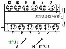


 1U-8869 Dial Indicator測量表
400-100-8969???15088860848
0574-26871589? 15267810868
0574-26886646? 15706865167
0574-26871569 18658287286